Cad Examples Based on college Textbook problems: Engineering Dynamics 12th edition RC Hibbeler
Prob...: Engineering Dynamics 12th edition RC Hibbeler Problem 19-55 MSC Adams Simulation Setting The Working Grid Opening Adams View Windows>...
Tuesday 29 October 2013
Engineering Dynamics 12th edition RC Hibbeler
Problem 19-55 MSC Adams Simulation
Setting The Working Grid
Opening Adams View
Windows>Programs>Msc Software>Adams x64 2013>aview
Change the length to metres
New Model>settings>units>length>metres

Press F4 to activate coordinate window
Go to toolbar and click settings gravity and set it to -9.81 in the y direction

Creating Parts
Go to main toolbox
Right click Link and select Rigid Body:Box
draw Box on ground
check length and set it to 0.7m
Right click on the working grid and the Locationevent appears and enter this coordinate to draw first point(0,0,-0.1)draw the first point of the box and drag the cursor downward to place the second point of the box
Go to main toolbox
Right click Box and select Rigid Body:Link
length to 0.09m(check the box)
width to 4.0cm(check the box)
depth to 2.0cm(check the box)
Press enter
Move mouse cursor on to the drawing area and draw the first point at the origin(look for the coordinate window,it will help out when drawing the first point of the link)
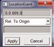
Right click on drawing area the loctionevent box will appear and enter this coordinates(0,0.009,0) for the second point of the link and press enter
Press F to fit the drawing on the drawing window
Change the link type from 'on ground' to new part
Set length to 0.6m and press enter
Draw first point of link(Rod) at he marker 2 of first link and move cursor until the Rod stays vertical
Right Click on link 2 and rename it 'Rod'
Press F to fit
Right click on Rod and go to Part>Modify>Define Mass by>User Input and set mass to 3 kg and click OK
Go to main toolbox Right click at the link icon and select Rigid Body:Sphere
check radius box and set radius to 0.09m and draw the sphere at the top of the rod,move the cursor around the top marker of the Rod until the marker name is displayed as a guidance for you and attach the sphere there
Right click on the sphere and rename it 'Pendulum' and set its mass to 5Kg
Right click at the main toolbox and click construction geometry:point
Draw a point at (0.7,0.09,0) using the locationEvent
Right click the measure icon at the main toolbox and select the angle measuring icon
To place the angle measuring tool select the first point at the marker point where the sphere joins the rod(0,0.69,0),the second point where the rod joins the first link(0,0.009,0)and the final point and the point created earlier on at (0.7,0.09,0)
Creating Joints

Right click joints at the main ToolBox and select fixed joint,to select the bodies first select the Pendulum and then the rod and the joint point at (0,0.69,0),lookout for the marker to help you place the joint
Right joints and select revolute joint and select the two bodies being the first link and the rod and the placement being at (0,0.009,0)
Go to Position at the main ToolBox and right click Position and select repositioning object relative to the working grid by entering coordinates,select both the Rod and Pendulum,go to orientation and set 1 to 89°..This is to make the pendulum fall,otherwise if its left at 90 degrees it wont fall due to gravity
Creating Contact

Go to main toolbox
Right click connector and select contact
go to contact type and select solid to solid
go to i solid(s) box and right click in it conctact solid>pick and click the pendulum to select it
go to j solid(s) box and right click in it conctact solid>pick and click the box to select it
go to normal force and select restitution,set coefficient of restitution as 0.8
click OK
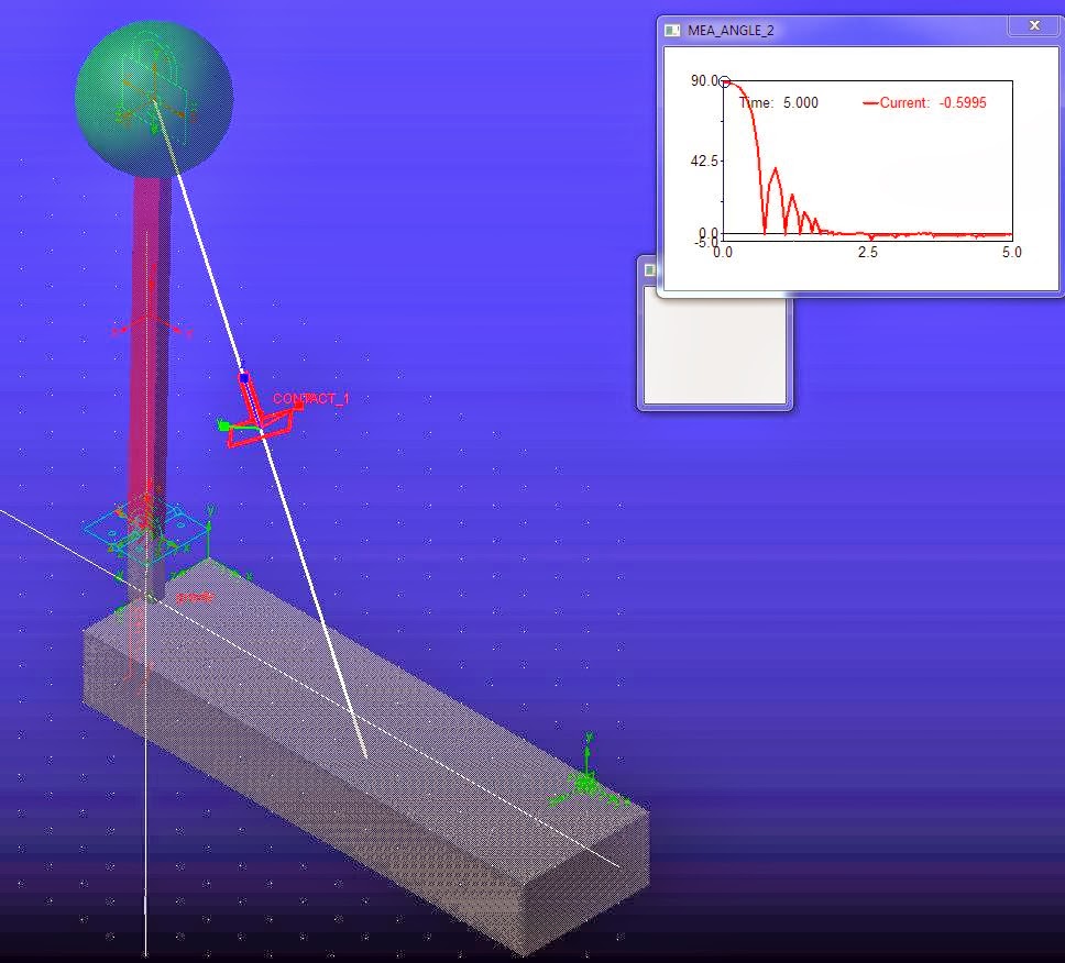
Click render at the bottom of the main toolbox and you should end up having something similar to this

Running Simulation
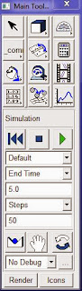
Go to main toolbox
Click Interactive simulation
Set end time to 5 seconds and steps to 50
Click Start simulation
After the simulation stops right click on the graph/strip curve plot:scht1>transfer to full plot to display the graph in full window
Once at the plot full window click the track plot icon on the toolbar and place the tracking object at the first maximum rise of the graph thats the rebound angle after the sphere strikes the floor which is about 38 degrees

This is intended for engineering students to help them in understanding concepts much better by solving problems graphicaly cause i have realised that simulatying the problems helps in really understanding the theory.
More simulations to come from problems in college textbooks..Stress Analysis,Engineering Dynamics,Engineering Statics,Circuit Analysis etc...From books written by people such as RC Hibbeler,Beer Johnston,alexander Sadiku and othersSolidworks,Ansys,Pspice/Cadence,Labview,Matlab etc.keep tabs on this blog..Feel free to comment and ask questions,let me know of any erros..just anything
Problem 19-55 MSC Adams Simulation
Setting The Working Grid
Opening Adams View
Windows>Programs>Msc Software>Adams x64 2013>aview
Change the length to metres
New Model>settings>units>length>metres

Press F4 to activate coordinate window
Go to toolbar and click settings gravity and set it to -9.81 in the y direction
Creating Parts
Go to main toolbox
Right click Link and select Rigid Body:Box
draw Box on ground
check length and set it to 0.7m
Right click on the working grid and the Locationevent appears and enter this coordinate to draw first point(0,0,-0.1)draw the first point of the box and drag the cursor downward to place the second point of the box
Go to main toolbox
Right click Box and select Rigid Body:Link
length to 0.09m(check the box)
width to 4.0cm(check the box)
depth to 2.0cm(check the box)
Press enter
Move mouse cursor on to the drawing area and draw the first point at the origin(look for the coordinate window,it will help out when drawing the first point of the link)
Right click on drawing area the loctionevent box will appear and enter this coordinates(0,0.009,0) for the second point of the link and press enter
Press F to fit the drawing on the drawing window
Change the link type from 'on ground' to new part
Set length to 0.6m and press enter
Draw first point of link(Rod) at he marker 2 of first link and move cursor until the Rod stays vertical
Right Click on link 2 and rename it 'Rod'
Press F to fit
Right click on Rod and go to Part>Modify>Define Mass by>User Input and set mass to 3 kg and click OK
Go to main toolbox Right click at the link icon and select Rigid Body:Sphere
check radius box and set radius to 0.09m and draw the sphere at the top of the rod,move the cursor around the top marker of the Rod until the marker name is displayed as a guidance for you and attach the sphere there
Right click on the sphere and rename it 'Pendulum' and set its mass to 5Kg
Right click at the main toolbox and click construction geometry:point
Draw a point at (0.7,0.09,0) using the locationEvent
Right click the measure icon at the main toolbox and select the angle measuring icon
To place the angle measuring tool select the first point at the marker point where the sphere joins the rod(0,0.69,0),the second point where the rod joins the first link(0,0.009,0)and the final point and the point created earlier on at (0.7,0.09,0)
Creating Joints

Right click joints at the main ToolBox and select fixed joint,to select the bodies first select the Pendulum and then the rod and the joint point at (0,0.69,0),lookout for the marker to help you place the joint
Right joints and select revolute joint and select the two bodies being the first link and the rod and the placement being at (0,0.009,0)
Go to Position at the main ToolBox and right click Position and select repositioning object relative to the working grid by entering coordinates,select both the Rod and Pendulum,go to orientation and set 1 to 89°..This is to make the pendulum fall,otherwise if its left at 90 degrees it wont fall due to gravity
Creating Contact

Go to main toolbox
Right click connector and select contact
go to contact type and select solid to solid
go to i solid(s) box and right click in it conctact solid>pick and click the pendulum to select it
go to j solid(s) box and right click in it conctact solid>pick and click the box to select it
go to normal force and select restitution,set coefficient of restitution as 0.8
click OK
Click render at the bottom of the main toolbox and you should end up having something similar to this

Running Simulation
Go to main toolbox
Click Interactive simulation
Set end time to 5 seconds and steps to 50
Click Start simulation
After the simulation stops right click on the graph/strip curve plot:scht1>transfer to full plot to display the graph in full window
Once at the plot full window click the track plot icon on the toolbar and place the tracking object at the first maximum rise of the graph thats the rebound angle after the sphere strikes the floor which is about 38 degrees

This is intended for engineering students to help them in understanding concepts much better by solving problems graphicaly cause i have realised that simulatying the problems helps in really understanding the theory.
More simulations to come from problems in college textbooks..Stress Analysis,Engineering Dynamics,Engineering Statics,Circuit Analysis etc...From books written by people such as RC Hibbeler,Beer Johnston,alexander Sadiku and othersSolidworks,Ansys,Pspice/Cadence,Labview,Matlab etc.keep tabs on this blog..Feel free to comment and ask questions,let me know of any erros..just anything
Subscribe to:
Posts (Atom)